

Fundamentals
Discover the Fundamentals of Our Product Systems
Chemical metal deposition ensures a very consistent and uniform layer thickness distribution, even for components with complex geometry.
Chemical Nickel
Chemical Nickel as a Basis
Unlike electrolytic deposition, chemical nickel coating takes place without an external power source, i.e. by purely chemical means.
This results in the special properties of these layers: chemical metal deposition ensures a very consistent and uniform layer thickness distribution, even for components with complex geometry. Internal geometries, bores, and undercuts are also coated absolutely uniformly.
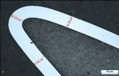
Chemical Nickel
A reducing agent is required to deposit chemical nickel layers. In most cases, this is a phosphorus-containing compound. Due to the process, part of the phosphorus is incorporated into the layer during the coating process, resulting in a nickel alloy layer (Ni-P).
The phosphorus content of the layer, and thus also the layer properties, can be specifically adjusted. Depending on the phosphorus content, the following coating systems are distinguished:
CHEMICAL NICKEL LOW PHOS
Layers typically have a phosphorus content between 1–5%. Even in the as-deposited state, the layers already have a high hardness of about 750 HV 0.1 and are particularly suitable for wear protection of temperature-sensitive substrates. Typical substrate materials are therefore aluminum and hardened steels, since heat treatment at temperatures above 150 °C can lead to undesirable microstructural changes and a drop in hardness here.
Layers can be deposited with a high gloss. Heat treatment at temperatures above approx. 150–400 °C increases layer adhesion and layer hardness by up to 250 HV.
Chemical Nickel Mid Phos
Layers typically have a phosphorus content between 5–10%. In the as-deposited state, the layers have a high hardness of about 550 HV 0.1 and are particularly suitable for use in dispersion layers and deposition on all substrates. Typical substrate materials are aluminum and all types of steels and special materials.
Heat treatment at temperatures above approx. 150–400 °C increases layer adhesion and layer hardness by up to 250 HV.
Chemical Nickel High Phos
Layers typically have a phosphorus content between 10–13%. In the as-deposited state, the layers have a hardness of about 500 HV 0.1, which can be increased to about 950 HV 0.1 through heat treatment. These layers exhibit outstanding corrosion resistance.
Heat treatment at temperatures above approx. 150–400 °C increases layer adhesion and layer hardness by up to 250 HV.
DIAPROTECT Fundamentals
CHEMICAL NICKEL – DIAMOND MMD / PMD Is the Basis of DIAPROTECT
Layers have been used successfully for decades, particularly in the textile machinery sector. Synthetic diamonds with an average particle size of 2 µm are preferably embedded. The layers are characterized by excellent resistance to abrasive wear and, thanks to their heterogeneous layer structure, offer the unique ability to set defined friction values that remain constant over the service life of the layer.
These properties are used in particular for coating fiber-guiding components in the textile machinery sector.
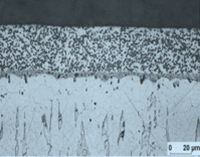
Cross-section: Chemical Nickel – Diamond
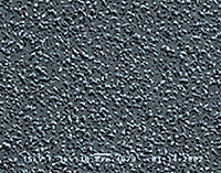
Surface Topography: Chemical Nickel – Diamond
Chemical Nickel - Diamond ND
In these newly developed dispersion layers, nanodiamonds are embedded in the chemical nickel layer. The primary particle size of the diamonds is only 4-6 nm.
The incorporation of the nanoparticles occurs almost agglomerate-free. Although the incorporation rate is only 0.2–0.3%, the properties of the chemical nickel layers are dramatically altered. Resistance to abrasive wear is significantly increased, as demonstrated by studies using the Taber Abraser test.
Particularly for Low and Mid Phos layers, the incorporation of nanodiamonds achieves a significant improvement in wear resistance even without heat treatment.
Since the small particle size means no wear effect is exerted on the tribological counterpart, these layers are particularly suitable for use in closed tribological systems.
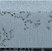
Focused Ion Beam: Chemical Nickel – ND
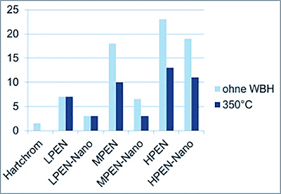
Taber Wear Index (wear in mg after 1000 cycles)
Friction wheel: CS 10
Load: 1000g
Cycles 6*1000
DIAGRIP Fundamentals
CHEMICAL NICKEL – DIAMOND Is the Basis of DIAGRIP
At CCT, the Diagrip® layers make use of the ability to specifically increase the friction values of a surface through the incorporation of diamond particles. This has particular advantages for force-fit connections. Among the known types of connections, a distinction is made between form-fit, material-locking, friction-locking, or combinations of the connection types mentioned.
The transmission capability of a friction-locking connection is limited by the design, the surface pressure, and the material-specific coefficient of friction. However, a targeted increase in friction can achieve an increase in force transmission without structural changes to the component. This is made possible through the use of Diagrip® friction-increasing surface layers.
Diagrip® is a chemical nickel matrix with embedded diamonds of defined size and concentration.
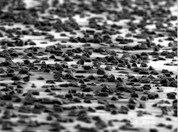
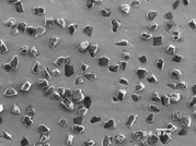
Diagrip – Surface in Oblique View and Top View
The layers can be applied either to thin foils made of steel or composite materials, or directly to a component.
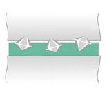
When using Diagrip® foils or direct coatings, increases in transferable forces of up to 300% are achieved compared to the initial state. This effect is based on the diamond particles penetrating the mating surfaces. This creates a micro form-fit between the base and mating body, which depends on the material, surface, and surface pressure of the joining partners. This model concept is illustrated below.
Diagrip® layers are used wherever efficient and safe force transmission is the priority. Due to their excellent properties, they are the first choice in the automotive and mechanical engineering industries as well as in drive technology. This includes:
- Transmission of the highest forces and torques
- Reliable increase in the coefficient of friction
- Maximum level of safety and reproducibility
- Availability as foils or direct coatings according to customer specification
- Trouble-free reassembly
- The effect of Diagrip® is not affected by thin oil films or preservatives
DIAGLIDE Fundamentals
CHEMICAL NICKEL SILICON CARBIDE Is the Basis of DIAGLIDE
Chemical Nickel – SiC layers are used for coating textile machinery, printing machinery, and engine components.
Silicon carbide is a synthetically produced hard material characterized by high hardness and a rather splintery grain shape compared to diamond.
Chemical Nickel – SiC layers exhibit outstanding wear protection properties and, after mechanical post-treatment through vibratory finishing or honing, are particularly suitable as a tribological partner in sliding-stress applications.
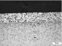
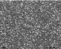
Chemical Nickel – SiC (particle size 1-4 µm)
DIAPROTECT Fundamentals
CHEMICAL NICKEL BORON CARBIDE Is the Basis of DIAPROTECT
Chemical Nickel – B4C layers are used for coating textile machinery, printing machinery, and engine components. Boron carbide is a synthetically produced hard material characterized by high hardness and special chemical-physical properties.
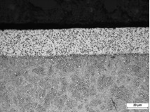
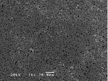
Chemical Nickel – Boron Carbide (particle size 2 µm)
DIASHIELD Fundamentals
CHEMICAL NICKEL – DISPERSION LAYERS with Embedded Solid Lubricants Are the Basis of DIASHIELD
These coating systems are preferably used when adhesive wear is to be prevented in sliding-stress tribological systems. The lubricating effect of the embedded solid lubricants is based on the fact that, during the sliding process, they separate the two contact surfaces by forming intermediate layers and/or alter them in such a way that no direct metal/metal contact, and thus no wear, can occur.
The lubricating effectiveness of PTFE is based on the formation of an adhesive bond in the friction contact. PTFE molecules are sheared, creating a transfer film in the contact zone.
CHEMICAL NICKEL – PTFE / HBN
Due to the low hardness of the embedded particles, chemical nickel – PTFE layers show comparatively low resistance to abrasive wear. The thermal curing of the layers is limited to about 290 °C due to the temperature sensitivity of the PTFE particles. This temperature limit naturally also considerably limits the thermal application range of such coating systems.
Under suitable operating conditions, chemical nickel – PTFE layers show a very low coefficient of friction even in the unlubricated state, as well as a marked reduction in the stick-slip effect. Also worth mentioning are the pronounced anti-adhesive properties of the layer, which can be used in many technical applications.
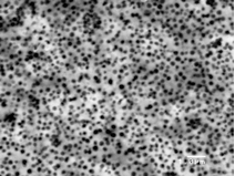
Cross-section Chem. Nickel – PTFE (particle size 0.5 µm)
Contact
Your Inquiry
Do you have questions about our product systems or fields of application? We would be happy to advise you comprehensively via our contact form.