
The electroless metal deposition ensures a very constant and even coating distribution, even on components with complex geometries.
- ELECTROLESS NICKEL AS THE BASIS
- DIAPROTECT Basics
- DIAGRIP Basics
- DIAGLIDE Basics
- DIAPROTECT Basics
- DIASHIELD Basics
This process results in the unique characteristics of these layers:
The electroless metal deposition ensures a very constant and even coating distribution, even on components with complex geometries.
Internal geometries, drill holes, and undercuts are also coated with an absolutely even layer.
A reduction agent is required to depot the electroless nickel layers. In most cases, this is a compound containing phosphorous. Some of the phosphorous is embedded in the coating during the coating process due to the procedure used, forming a nickel alloy layer (Ni-P).
The phosphorous content of the layer, and thereby the layer properties, can be adjusted in a targeted fashion. We can differentiate between the following layer systems, depending on the phosphorous content:
ELECTROLESS NICKEL LOW PHOS
Generally, coatings have a phosphorous content between 1 – 5 %. The layers already have a high level of hardness when they are deposited of around 750 HV 0.1, and are particularly well-suited to provide wear protection to temperature-sensitive substrates. Typical substrate materials, therefore, include aluminium and hardened steel, since heat treatment of these materials at temperatures over 150 °C can cause undesirable structural changes and a reduction in hardness.
Layers can be deposited with a high-gloss appearance. Heat treatment at temperatures above approx. 150 – 400 °C increases coating adhesion and coating hardness by up to 250 HV.
| P content | 1-5 % |
| Hardness at depositing | 725 – 800 HV 0.05 |
| “Hardness after heat treatment [350° / 2h]” |
950 – 1050 HV 0.05 |
| Wear resistance Taber Abraser CS 10 [mg / 1000 cycles] | |
| At depositing | 6 – 10 |
| After heat treatment [350°C / 2h] | 5 – 9 |
| Tensile strength [MPa] | 200 – 400 |
| Elongation at break [%] | 0.5 – 1.5 |
| Young’s modulus [GPa] | 55 – 65 |
| Residual stress on steel substrate | Slight residual compressive stress |
| Melting point [°C] | 1250 – 1350 |
| Spec. electrical resistance [µΩ*cm] | 10 – 30 |
| “Thermal expansion coefficient [µm /m / K]” |
12 – 15 |
| Thermal conductivity | |
| Coercive field strength [Oe] | 15 – 80 |
| Magnetic properties of the layer | magnetic |
ELECTROLESS NICKEL MID PHOS
Generally, coatings have a phosphorous content between 5 – 10 %. The layers have a high level of hardness when they are deposited of around 550 HV 0.1, and are particularly well-suited for use in dispersion coatings and for deposition on all substrates. Typical substrate materials include aluminium and all kinds of steels and specialized materials.
Heat treatment at temperatures above approx. 150 – 400 °C increases coating adhesion and coating hardness by up to 250 HV.
| P-Content | 5-10 % |
| Hardness at depositing | 500 – 600 HV 0.05 |
| “Hardness after heat treatment [350° / 2h]” |
950 – 1050 HV 0.05 |
| Wear resistance Taber Abraser CS 10 [mg / 1000 cycles] | |
| At depositing | 15 – 20 |
| After heat treatment [350°C / 2h] | 10 – 12 |
| Tensile strength [MPa] | 800 – 1000 |
| Elongation at break [%] | 0.5 – 1.0 |
| Young’s modulus [GPa] | 50 – 65 |
| Residual stress on steel substrate | Neutral / slight residual tensile stresses |
| Melting point [°C] | 880 – 980 |
| Spec. electrical resistance [µΩ*cm] | 40 – 70 |
| “Thermal expansion coefficient [µm /m / K]” |
10 – 15 |
| Thermal conductivity | |
| Coercive field strength [Oe] | 1 – 8 |
| Magnetic properties of the layer | weakly magnetic |
ELECTROLESS NICKEL HIGH PHOS
Generally, coatings have a phosphorous content between 10 – 13 %. The layers have a hardness of around 500 HV 0.1 when they are deposited, which can be increased to around 950 HV 0.1 through heat treatment. These coatings have outstanding corrosion resistance.
Heat treatment at temperatures above approx. 150 – 400 °C increases coating adhesion and coating hardness by up to 250 HV.
| P-Content | 10-13 % |
| Hardness at depositing | 450 – 525 HV 0.05 |
| “Hardness after heat treatment [350° / 2h]” |
850 – 950 HV 0.05 |
| Wear resistance Taber Abraser CS 10 [mg / 1000 cycles] | |
| At depositing | 22 – 24 |
| After heat treatment [350°C / 2h] | 10 – 14 |
| Tensile strength [MPa] | 650 – 900 |
| Elongation at break [%] | 1.0 – 2.5 |
| Young’s modulus [GPa] | 55 – 70 |
| Residual stress on steel substrate | Neutral / slight residual compressive stresses |
| Melting point [°C] | 880 – 900 |
| Spec. electrical resistance [µΩ*cm] | 75 – 110 |
| “Thermal expansion coefficient [µm /m / K]” |
08 – 10 |
| Thermal conductivity | |
| Coercive field strength [Oe] | 0 |
| Magnetic properties of the layer | Non-magnetic |
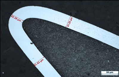
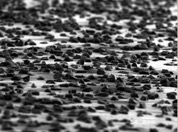
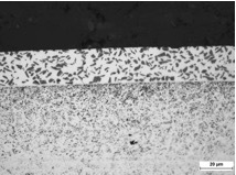
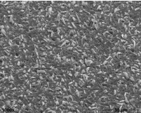
Layers have been used successfully for decades, particularly in the textile machine sector. Synthetic diamonds with an average particle size of 2 µm are preferred. The layers are characterized by excellent resistance to abrasive wear and, thanks to their heterogeneous layer structure, offer the unique possibility of setting defined friction values that are constant over the life of the layer.
These properties are used in particular when coating fiber-guiding components in the textile machine sector.
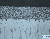
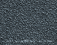
Cross section: Electroless nickel – diamond Surface topography: Electroless nickel – diamond
| P-content | Depending on requirements |
| Grain size diamond d50 | 2 µm [4 µm; 6 µm; 10 µm] |
| Storage volume | 25-30 % |
| Layer thickness | usually 15-50 µm |
| Hardness of deposition | up to 750 HV 0.01 |
| Hardness after heat treatment [350° / 2h] | up to 1300 HV 0.01 |
| Wear resistance Taber Abraser CS 10 [mg / 1000 cycles] | |
| Separation state | 0.5 – 1.5 |
| After heat treatment [350 ° C / 2h] | < 1.5 |
| Operating temperature | up to 500 °C |
CHEMICAL NICKEL – DIAMOND ND
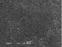
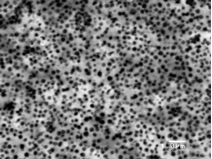
With these newly developed dispersion layers, nanodiamonds are embedded in the chemical nickel layer. The primary particle size of the diamonds is only 4-6 nm.
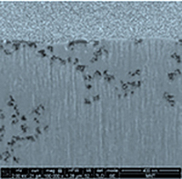
Focused Ion Beam: Electroless Nickel – ND
The storage of the nanoparticles takes place almost free of agglomerates. Although the storage rate is only 0.2 – 0.3%, the properties of the electroless nickel layers are significantly changed. The resistance to abrasive wear is significantly increased, as studies with the Taber Abraser test show.
In the case of low and mid Phos layers in particular, the inclusion of nanodiamonds results in a significant improvement in wear resistance, even without heat treatment.
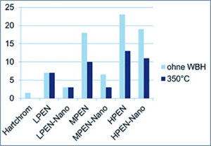
Taber Wear Index (wear in mg. After 1000 cycles)
Friction roller: CS 10
load: 1000g
cycles 6 * 1000
Since the small particle size means that there is no wear and tear on the tribological counterpart, these layers are particularly suitable for use in closed tribological systems.
CHEMICAL NICKEL – DIAMOND is the basis of DIAGRIP
With the Diagrip® layers from CCT, the possibility is used to increase the coefficient of friction of a surface in a targeted manner by embedding diamond particles. This has particular advantages in the case of non-positive connections. In the known types of connection, a distinction is made between form-fitting, material-locking, frictional-locking or combinations of the connection types mentioned.
The transmission capacity of a frictional connection is limited by the design, the surface pressure and the material-specific coefficient of adhesion. However, through a targeted increase in friction, an increase in power transmission can be achieved without constructive changes to the component. This is made possible by the use of Diagrip® friction-increasing surface layers.
Diagrip® is an electroless nickel matrix with embedded diamonds of a defined size and concentration.
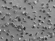
Diagrip – surface in oblique view and top view
The layers can either be applied to thin foils made of steel or composite materials or directly to a component.
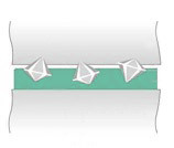
When using Diagrip® foils or direct coatings, increases in the transferable forces of up to 300% are achieved compared to the initial state. This effect is based on the penetration of the diamond particles into the opposing surfaces. This creates a micro-form fit between the main body and the mating body, which depends on the material, surface and surface pressure of the joint partners. This model is illustrated below.
Diagrip® layers are used wherever efficient and safe power transmission is in the foreground. Due to their excellent properties, they are the first choice in automotive and mechanical engineering as well as in drive technology. These include:
- Transmission of highest forces and torques
- Reliable increase in the coefficient of adhesion
- Maximum safety and reproducibility
- Possibility of foils or direct coatings according to customer specifications
- Problem-free reassembly
- The effect of Diagrip® is not influenced by thin oil films or preservatives
Datasheet Diagrip – Foil
| Functional properties | Coefficient of friction increasing diamond coating on steel or composite foil |
| description | DIAGRIP®10 | DIAGRIP®25 | DIAGRIP®35 |
| Foil material | Steel C75 S or GRP foil |
| editing | Water jet cutting; Lasers or punching |
| colour | Metallic silver gray |
| Thickness of the foil x | 0,1 mm ± 0,01 mm or thicker |
| Medium particle size diamond | 10 µm | 25 µm | 35 µm |
| Area occupancy density | 10-20 % | 10-25 % | 15-30 % |
| Layer matrix | Electroless nickel |
| Hardness layer matrix | 550 – 950 HV0,1 |
| Layer thickness of the matrix y | 5-8 µm | 13-17 µm | 14-22 µm |
| Magnetic | When using GRP foils, non-magnetic foils can be produced |
| Electric conductivity | When using GRP foils, electrically insulating foils can be produced |
| requirements | |||
| Roughness Rz or | Rz < 10 µm | Rz < 25 µm | Rz < 35 µm |
| Mean roughness Rz of the mating surfaces | Rz < 1,6 µm | Rz < 3,2 µm | Rz < 6,3 µm |
| Min. Surface pressure | 50 MPa |
| Max. Operating temperature | 400 ° C for steel foils up to 200 ° C with GRP foil |
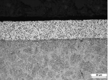
Electroless nickel – SiC – layers are used to coat textile machine, printing machine and engine components. Silicon carbide is a synthetically produced hard material that is characterized by its high hardness and a grain shape that is more splintery than diamond.
Electroless nickel – SiC layers show excellent wear protection properties and are particularly suitable as tribological partners in applications subject to sliding stress after mechanical post-treatment by vibratory grinding or honing.
Chemisch Nickel – SiC (Partikelgröße 1-4 µm)
| P-content | Depending on requirements |
| Grain size SiC d50 | 2 µm [0,5 µm] |
| Storage volume | 20-25 % |
| Layer thickness | usually 15-50 µm |
| Hardness of deposition | up to 750 HV 0.01 |
| Hardness after heat treatment [350° / 2h] | up to 1150 HV 0.01 |
| Wear resistance Taber Abraser CS 10 [mg / 1000 Zyklen] | |
| Separation state | |
| After heat treatment [350°C / 2h] | < 1.5 |
| Operating temperature up to 5 | 500 °C |
Chemical nickel – B4C – layers are used to coat textile machine, printing machine and engine components. Boron carbide is a synthetically produced hard material, which is characterized by high hardness and special chemical-physical properties.
Electroless nickel – boron carbide (particle size 2 µm)
| P-content | Depending on requirements |
| Grain size SiC d50 | 2 µm [0,5 µm] |
| Storage volume | 20-25 % |
| Layer thicknesse | usually 15-50 µm |
| Hardness of deposition | up to 750 HV 0.01 |
| Hardness after heat treatment [350° / 2h] | up to 1150 HV 0.01 |
| Wear resistance Taber Abraser CS 10 [mg / 1000 Zyklen] | |
| Separation state | |
| After heat treatment [350°C / 2h] | < 1.5 |
| Operating temperature up to 5 | 500 °C |
These layer systems are preferably used when adhesive wear is to be prevented in tribological systems subject to sliding stress. The lubricating effect of the embedded solid lubricants is based on the fact that they separate the two contact surfaces by forming intermediate layers during the sliding process and / or change them in such a way that no direct metal / metal contact and thus no wear can take place.
The lubricating effectiveness of PTFE is based on the creation of an adhesive bond in the frictional contact. PTFE molecules are sheared and a transfer film is created in the contact zone.
CHEMICAL NICKEL – PTFE / HBN
Due to the low hardness of the embedded particles, chemically nickel-PTFE layers show a comparatively low resistance to abrasive wear. The thermal curing of the layers is limited to around 290 ° C due to the temperature sensitivity of the PTFE particles. Of course, this temperature limit also considerably limits the range of thermal applications for such layer systems.
Under suitable conditions of use, the chemical nickel-PTFE layers show a very low coefficient of friction, even in the non-lubricated state, as well as a significant reduction in the stick-slip effect. Also worth mentioning are the pronounced anti-adhesive properties of the layer, which can be used in a variety of technical ways.
Cross-section Chem. Nickel – PTFE (Particle size 0.5 µm)
| P-content | Depending on requirements |
| Grain size PTFE d50 | 0,5 µm |
| Storage volume | 20-25 % |
| Layer thickness | usually 5-20 µm |
| Hardness of deposition | up to 350 HV 0.01 |
| Hardness after heat treatment [350° / 2h] | up to500 HV 0.01 |
| Wear resistance Taber Abraser CS 10 [mg / 1000 Zyklen] | |
| Separation stated | |
| After heat treatment [350°C / 2h] | |
| Operating temperature up to | 270 °C |
ELECTROLESS NICKEL AS THE BASIS
This process results in the unique characteristics of these layers:
The electroless metal deposition ensures a very constant and even coating distribution, even on components with complex geometries.
Internal geometries, drill holes, and undercuts are also coated with an absolutely even layer.
A reduction agent is required to depot the electroless nickel layers. In most cases, this is a compound containing phosphorous. Some of the phosphorous is embedded in the coating during the coating process due to the procedure used, forming a nickel alloy layer (Ni-P).
The phosphorous content of the layer, and thereby the layer properties, can be adjusted in a targeted fashion. We can differentiate between the following layer systems, depending on the phosphorous content:
ELECTROLESS NICKEL LOW PHOS
Generally, coatings have a phosphorous content between 1 – 5 %. The layers already have a high level of hardness when they are deposited of around 750 HV 0.1, and are particularly well-suited to provide wear protection to temperature-sensitive substrates. Typical substrate materials, therefore, include aluminium and hardened steel, since heat treatment of these materials at temperatures over 150 °C can cause undesirable structural changes and a reduction in hardness.
Layers can be deposited with a high-gloss appearance. Heat treatment at temperatures above approx. 150 – 400 °C increases coating adhesion and coating hardness by up to 250 HV.
| P content | 1-5 % |
| Hardness at depositing | 725 – 800 HV 0.05 |
| “Hardness after heat treatment [350° / 2h]” |
950 – 1050 HV 0.05 |
| Wear resistance Taber Abraser CS 10 [mg / 1000 cycles] | |
| At depositing | 6 – 10 |
| After heat treatment [350°C / 2h] | 5 – 9 |
| Tensile strength [MPa] | 200 – 400 |
| Elongation at break [%] | 0.5 – 1.5 |
| Young’s modulus [GPa] | 55 – 65 |
| Residual stress on steel substrate | Slight residual compressive stress |
| Melting point [°C] | 1250 – 1350 |
| Spec. electrical resistance [µΩ*cm] | 10 – 30 |
| “Thermal expansion coefficient [µm /m / K]” |
12 – 15 |
| Thermal conductivity | |
| Coercive field strength [Oe] | 15 – 80 |
| Magnetic properties of the layer | magnetic |
ELECTROLESS NICKEL MID PHOS
Generally, coatings have a phosphorous content between 5 – 10 %. The layers have a high level of hardness when they are deposited of around 550 HV 0.1, and are particularly well-suited for use in dispersion coatings and for deposition on all substrates. Typical substrate materials include aluminium and all kinds of steels and specialized materials.
Heat treatment at temperatures above approx. 150 – 400 °C increases coating adhesion and coating hardness by up to 250 HV.
| P-Content | 5-10 % |
| Hardness at depositing | 500 – 600 HV 0.05 |
| “Hardness after heat treatment [350° / 2h]” |
950 – 1050 HV 0.05 |
| Wear resistance Taber Abraser CS 10 [mg / 1000 cycles] | |
| At depositing | 15 – 20 |
| After heat treatment [350°C / 2h] | 10 – 12 |
| Tensile strength [MPa] | 800 – 1000 |
| Elongation at break [%] | 0.5 – 1.0 |
| Young’s modulus [GPa] | 50 – 65 |
| Residual stress on steel substrate | Neutral / slight residual tensile stresses |
| Melting point [°C] | 880 – 980 |
| Spec. electrical resistance [µΩ*cm] | 40 – 70 |
| “Thermal expansion coefficient [µm /m / K]” |
10 – 15 |
| Thermal conductivity | |
| Coercive field strength [Oe] | 1 – 8 |
| Magnetic properties of the layer | weakly magnetic |
ELECTROLESS NICKEL HIGH PHOS
Generally, coatings have a phosphorous content between 10 – 13 %. The layers have a hardness of around 500 HV 0.1 when they are deposited, which can be increased to around 950 HV 0.1 through heat treatment. These coatings have outstanding corrosion resistance.
Heat treatment at temperatures above approx. 150 – 400 °C increases coating adhesion and coating hardness by up to 250 HV.
| P-Content | 10-13 % |
| Hardness at depositing | 450 – 525 HV 0.05 |
| “Hardness after heat treatment [350° / 2h]” |
850 – 950 HV 0.05 |
| Wear resistance Taber Abraser CS 10 [mg / 1000 cycles] | |
| At depositing | 22 – 24 |
| After heat treatment [350°C / 2h] | 10 – 14 |
| Tensile strength [MPa] | 650 – 900 |
| Elongation at break [%] | 1.0 – 2.5 |
| Young’s modulus [GPa] | 55 – 70 |
| Residual stress on steel substrate | Neutral / slight residual compressive stresses |
| Melting point [°C] | 880 – 900 |
| Spec. electrical resistance [µΩ*cm] | 75 – 110 |
| “Thermal expansion coefficient [µm /m / K]” |
08 – 10 |
| Thermal conductivity | |
| Coercive field strength [Oe] | 0 |
| Magnetic properties of the layer | Non-magnetic |
Chem. Nickel Dispersion
CHEMISCH NICKEL – DIAMANT MMD / PMD
Schichten werden seit Jahrzehnten erfolgreich insbesondere im Textilmaschinenbereich eingesetzt. Bevorzugt werden synthetische Diamanten mit einer mittleren Partikelgröße von 2 µm eingelagert. Die Schichten zeichnen sich durch eine hervorragende Beständigkeit gegen Abrasivverschleiß aus und bieten durch ihren heterogenen Schichtaufbau die einzigartige Möglichkeit, definierte und über die Lebensdauer der Schicht konstante Reibwerte einzustellen.
Diese Eigenschaften nutzt man insbesondere bei der Beschichtung faserführender Komponenten im Textilmaschinenbereich.
Querschliff: Chemisch Nickel – Diamant Oberflächentopographie: Chemisch Nickel – Diamant
| P-Gehalt | Je nach Anforderung |
| Korngröße Diamant d50 | 2 µm [4 µm; 6 µm; 10 µm] |
| Einlagerungsvolumen | 25-30 % |
| Schichtdicke | üblicherweise 15-50 µm |
| Härte Abscheidezustand | bis 750 HV 0.01 |
| Härte nach Wärmebehandlung [350° / 2h] | bis 1300 HV 0.01 |
| Verschleißbeständigkeit Taber Abraser CS 10 [mg / 1000 Zyklen] | |
| Abscheidezustand | 0.5 – 1.5 |
| Nach Wärmebehandlung [350°C / 2h] | < 1.5 |
| Einsatztemperatur | bis 500 °C |
CHEMISCH NICKEL – DIAMANT ND
Bei diesen neu entwickelten Dispersionsschichten werden Nanodiamanten in die Chemisch Nickel – Schicht eingelagert. Die Primärpartikelgröße der Diamanten beträgt nur 4-6 nm.
Focused Ion Beam: Chemisch Nickel – ND
Die Einlagerung der Nanopartikel geschieht nahezu agglomeratfrei. Obwohl die Einlagerungsrate nur 0.2 – 0.3 % beträgt, werden die Eigenschaften der Chemisch Nickel – Schichten gravierend verändert. Die Beständigkeit gegen Abrasivverschleiß wird deutlich erhöht, wie Untersuchungen mit dem Taber-Abraser – Test belegen.
Insbesondere bei Low – und Mid Phos – Schichten wird durch die Einlagerung von Nanodiamanten eine signifikante Verbesserung der Verschleißbeständigkeit selbst ohne Wärmebehandlung erreicht.
Taber Wear Index (Verschleiß in mg. nach 1000 Zyklen)
Reibrolle: CS 10
Last: 1000g
Zyklen 6*1000
Da durch die geringe Partikelgröße keine Verschleißwirkung auf den tribologischen Gegenpartner ausgeübt wird, eignen sich diese Schichten besonders für den Einsatz in geschlossenen Tribosystemen.
Chem. Nickel Diagrip
CHEMISCH NICKEL – DIAMANT DIAGRIP
Bei den Diagrip® Schichten von CCT nutzt man die Möglichkeit, durch die Einlagerung von Diamantpartikeln die Reibwerte einer Oberfläche gezielt zu erhöhen. Das hat besondere Vorteile bei kraftschlüssigen Verbindungen. Bei den bekannten Verbindungsarten wird zwischen formschlüssigen, stoffschlüssigen, reibschlüssigen oder Kombinationen aus den genannten Verbindungsarten unterschieden.
Die Übertragungsfähigkeit einer reibschlüssigen Verbindung ist durch die Auslegung, die Flächenpressung und dem werkstoffspezifischen Haftkoeffizienten begrenzt. Durch eine gezielte Reibungserhöhung kann jedoch eine Steigerung der Kraftübertragung ohne konstruktive Veränderungen am Bauteil erreicht werden. Ermöglicht wird dies durch den Einsatz von Diagrip® reibungserhöhenden Oberflächenschichten.
Diagrip® ist eine Chemisch-Nickel Matrix mit eingelagerten Diamanten definierter Größe und Konzentration.
Diagrip – Oberfläche in Schrägansicht und Draufsicht
Die Schichten können entweder auf dünne Folien aus Stahl oder Verbundwerkstoffen oder direkt auf ein Bauteil aufgebracht werden.

Beim Verwenden von Diagrip® – Folien oder Direktbeschichtungen werden im Vergleich zum Ausgangszustand Steigerungen der übertragbaren Kräfte bis zu 300% erreicht. Dieser Effekt b asiert auf dem Eindringen der Diamantpartikel in die Gegenflächen. Zwischen Grund- und Gegenkörper entsteht so ein Mikroformschluss, der von Material, Oberfläche und Flächenpressung der Fügepartner abhängt. Diese Modellvorstellung wird in untenstehend verdeutlicht.
Zum Einsatz kommen Diagrip® Schichten überall da, wo effiziente und sichere Kraftübertragung im Vordergrund steht. Aufgrund ihrer exzellenten Eigenschaften sind sie erste Wahl im Automobil- und Maschinenbau sowie in der Antriebstechnik. Hierzu gehören:
- Übertragung von höchsten Kräften und Drehmomenten
- Zuverlässige Erhöhung des Haftbeiwertes
- Höchstmaß an Sicherheit und Reproduzierbarkeit
- Möglichkeit von Folien oder Direktbeschichtungen gemäß Kundenspezifikation
- Problemlose Wiedermontage
- Die Wirkung von Diagrip® wird durch dünne Ölfilme oder Konservierungsmittel nicht beeinflusst
Datenblatt Diagrip – Folie
| Funktionale Eigenschaften | Reibwerterhöhende Diamantbeschichtung auf Stahl- oder Composite – Folie |
| Bezeichnung | DIAGRIP®10 | DIAGRIP®25 | DIAGRIP®35 |
| Folienmaterial | Stahl C75 S oder GFK – Folie |
| Bearbeitung | Wasserstrahlschneiden; Lasern oder Stanzen |
| Farbe | Silbrig grau metallisch |
| Dicke der Folie x | 0,1 mm ± 0,01 mm oder dicker |
| Mittlere Partikelgröße Diamant | 10 µm | 25 µm | 35 µm |
| Flächenbelegungsdichte | 10-20 % | 10-25 % | 15-30 % |
| Schichtmatrix | Chemisch Nickel |
| Härte Schichtmatrix | 550 – 950 HV0,1 |
| Schichtdicke der Matrix y | 5-8 µm | 13-17 µm | 14-22 µm |
| Magnetisch | Bei Verwendung von GFK – Folien können unmagnetische Folien hergestellt werden |
| Elektrische Leitfähigkeit | Bei Verwendung von GFK – Folien können elektrisch isolierende Folien hergestellt werden |
| Anforderungen | |||
| Rautiefe Rz oder | Rz < 10 µm | Rz < 25 µm | Rz < 35 µm |
| Mittenrauwert Ra der Gegenflächen | Rz < 1,6 µm | Rz < 3,2 µm | Rz < 6,3 µm |
| Min. Flächenpressung | 50 MPa |
| Max. Einsatztemperatur | 400 °C bei Stahlfolien bis 200 °C bei GFK – Folie |
Chem. Nickel Siliziumcarbid
CHEMISCH NICKEL SIZILIUMCARBID
Chemisch Nickel – SiC – Schichten werden zur Beschichtung von Textilmaschinen-, Druckmaschinen- und Motorenkomponenten eingesetzt.
Siliziumcarbid ist ein synthetisch hergestellter Hartstoff, der sich durch eine hohe Härte und eine im Vergleich zum Diamant eher splittrige Kornform auszeichnet.
Chemisch Nickel – SiC – Schichten zeigen hervorragende Verschleißschutzeigenschaften und eignen sich nach einer mechanischen Nachbehandlung durch Gleitschleifen oder Honen besonders als tribologischer Partner in gleitbeanspruchten Anwendungen.
Chemisch Nickel – SiC (Partikelgröße 1-4 µm)
| P-Gehalt | Je nach Anforderung |
| Korngröße SiC d50 | 2 µm [0,5 µm] |
| Einlagerungsvolumen | 20-25 % |
| Schichtdicke | üblicherweise 15-50 µm |
| Härte Abscheidezustand | bis 750 HV 0.01 |
| Härte nach Wärmebehandlung [350° / 2h] | bis 1150 HV 0.01 |
| Verschleißbeständigkeit Taber Abraser CS 10 [mg / 1000 Zyklen] | |
| Abscheidezustand | |
| Nach Wärmebehandlung [350°C / 2h] | < 1.5 |
| Einsatztemperatur bis 5 | 500 °C |
Chem. Nickel Borcarbid
CHEMISCH NICKEL BORCARBID
Chemisch Nickel – B4C – Schichten werden zur Beschichtung von Textilmaschinen-, Druckmaschinen- und Motorenkomponenten eingesetzt. Borcarbid ist ein synthetisch hergestellter Hartstoff, der sich durch eine hohe Härte und besondere chemisch-physikalische Eigenschaften auszeichnet.
Chemisch Nickel – Borcarbid (Partikelgröße 2 µm)
| P-Gehalt | Je nach Anforderung |
| Korngröße SiC d50 | 2 µm [0,5 µm] |
| Einlagerungsvolumen | 20-25 % |
| Schichtdicke | üblicherweise 15-50 µm |
| Härte Abscheidezustand | bis 750 HV 0.01 |
| Härte nach Wärmebehandlung [350° / 2h] | bis 1150 HV 0.01 |
| Verschleißbeständigkeit Taber Abraser CS 10 [mg / 1000 Zyklen] | |
| Abscheidezustand | |
| Nach Wärmebehandlung [350°C / 2h] | < 1.5 |
| Einsatztemperatur bis 5 | 500 °C |
Chem. Nickel PTFE/HBN
CHEMISCH NICKEL – DISPERSIONSSCHICHTEN MIT EINGELAGERTEN FESTSCHMIERSTOFFEN
Diese Schichtsysteme finden bevorzugt Anwendung, wenn in gleitbeanspruchten tribologischen Systemen Adhäsivverschleiß verhindert werden soll. Die Schmierwirkung der eingelagerten Festschmierstoffe beruht darauf, dass sie während des Gleitvorganges die beiden Kontaktflächen durch Bildung von Zwischenschichten trennen und / oder diese so verändern, dass kein direkter Metall / Metall-Kontakt und damit kein Verschleiß stattfinden kann.
Die Schmierwirksamkeit von PTFE beruht auf der Entstehung einer adhäsiven Bindung im Reibkontakt. PTFE – Moleküle werden geschert und es entsteht ein Transferfilm in der Kontaktzone.
CHEMISCH NICKEL – PTFE / HBN
Chemisch Nickel – PTFE – Schichten zeigen durch die geringe Härte der eingelagerten Partikel eine vergleichsweise geringe Beständigkeit gegen Abrasivverschleiß . Die thermische Aushärtung der Schichten ist durch die Temperaturempfindlichkeit der PTFE-Partikel auf etwa 290 °C begrenzt. Diese Temperaturgrenze limitiert natürlich auch das thermische Einsatzspektrum solcher Schichtsysteme erheblich.
Bei geeigneten Einsatzbedingungen zeigen die Chemisch Nickel – PTFE – Schichten einen sehr niedrigen Reibwert auch im ungeschmierten Zustand sowie eine deutliche Reduzierung des Stick-Slip – Effektes. Ebenfalls erwähnenswert sind die ausgeprägten antiadhäsiven Eigenschaften der Schicht, die technisch vielfältig genutzt werden können.
Querschliff Chem. Nickel – PTFE (Partikelgröße 0.5 µm)
| P-Gehalt | Je nach Anforderung |
| Korngröße PTFE d50 | 0,5 µm |
| Einlagerungsvolumen | 20-25 % |
| Schichtdicke | üblicherweise 5-20 µm |
| Härte Abscheidezustand | bis 350 HV 0.01 |
| Härte nach Wärmebehandlung [350° / 2h] | bis 500 HV 0.01 |
| Verschleißbeständigkeit Taber Abraser CS 10 [mg / 1000 Zyklen] | |
| Abscheidezustand | |
| Nach Wärmebehandlung [350°C / 2h] | |
| Einsatztemperatur bis | 270 °C |